6/22/07
Ganging Antennas
How to combine antennas that point in the same direction
As described on the previous page, when a 2-way splitter is used as a combiner,
1. one quarter of the input power is reflected back towards the input,
2. one quarter of the input power is diverted to the other input, and
3. one half of the input power is forwarded to the intended load.
These numbers assume the splitter is 100% efficient, and that the antennas point in different directions.
But something different happens when both antennas point at the same station...
Superposition
Superposition is the technique for analyzing
circuits that have multiple sources: You
simply determine the output with the inputs activated one at a time, and then
add together all the results. (By the Rules of Superposition
you may sum voltages or currents but you must not sum power.)
If half of the input power is forwarded to the load, the load voltage will be smaller than the input voltage by 0.707. (In an all-75W system, the power change is the square of the voltage change. The square root of 0.5 is 0.707.) Superposition says that if both inputs supply the same power, the voltage at the load will be 0.707+0.707=1.414. 1.414 squared is 2, which means there is twice the power at the load as was supplied at each input.
But you ask, “How can the power at the load equal the total input power if some of the power was reflected backwards?” The answer is that superposition applies to currents as well as voltages. The phase of the reflected currents is such that they subtract instead of add. The reflected currents will cancel each other out completely.
The doubling of the output power is equivalent to a 3 dB increase in the signal. If the combiner is 90% efficient then a 2.5 dB gain is seen. Note the dichotomy:
· If the antennas point in different directions, there is a 3.5 dB loss at the combiner.
· If the antennas point in the same direction, there is a 2.5 dB gain at the combiner.
This is a 6 dB swing. 3 dB of this is just the adding of the second antenna, but the other 3 dB is from the combiner becoming a much more effective device.
Avoiding a large loss at the combiner requires the complete cancellation of the reflected currents. This requires that both input signals be identical in amplitude and phase. This generally demands that the two antennas be identical, and that the two feedline delays be equal. Furthermore, both antennas must be in fields of equal strength, pointing the same direction, and must be positioned for proper phase. Making all this true for non-identical antennas is not practical.
Other gangs
When ganging N antennas using an N-way splitter, the same thing happens. If an N-way splitter will not cause reflections when used as a splitter then that device will not cause reflections when used as a combiner if all the input signals are identical.
Ganging three antennas requires finding a 3-way splitter that is completely symmetric. This author doesn’t know how prevalent these are. (Some 3-way splitters just contain two 2-way splitters, so one output is stronger than the others. Avoid that type.)
2-way, 4-way, and 8-way gangs are common. Successful gangs of other numbers are very uncommon.
For a 4-way gang, there is a trick for eliminating the combiner, but it only works for balanced line such as 300-ohm twinlead:
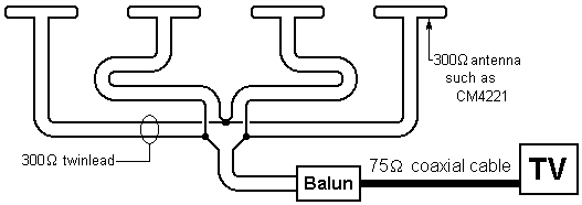
The “two in series, two in parallel” connection maintains 300 ohms. If well constructed, there is no loss whatsoever. A variation on this is to connect all four antennas in parallel and use a 1-to-1 balun.
The Two-Antenna Trick (outdoor version)
Using two antennas gives you some beam shaping options. You can create an antenna system that has:
· two or more strong beams (and no 3 dB splitter loss).
· a null in a controlled direction.
This technique applies to any pair of identical antennas, but 4-bay antennas are usually the best choice for this. Before trying this you probably should read through The Two-Antenna Trick (indoor version) since all the principles described there apply here. A 16-Bay UHF antenna also contains relevant information.
The following diagram shows the spacing (center to center) necessary to achieve lobes (beams) and nulls in the desired directions.
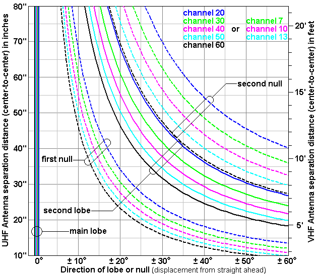
The solid lines are for lobes, and the dotted lines are for nulls. But if you reverse the polarity of one antenna (so that they subtract) then the dotted lines are for lobes and the solid lines are for nulls. (The graph was created for isotropic antennas. For practical antennas, the peaks of the side lobes are usually at a couple degrees less than what the graph says.)
The following examples are all difficult cases, probably requiring a hilltop location for DTV reception.
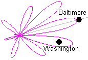
Example 1: Frederick, Maryland 21709
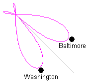 The
compass directions for Baltimore and Washington are 50 degrees apart. Point both antennas half way between
Baltimore and D.C. and reverse the polarity of one antenna. The graph says mount the antennas 23 inches
apart, mast-to-mast. At channel 40, the
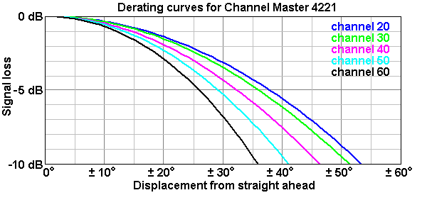
antenna will have two equal main lobes 25 degrees from the centerline. The de-rating curves below show that the
25-degree aiming error is costing 3 dB, so the performance is no better than a
4-bay pointed at one city. (The
performance is about the same as two 8-bays pointed in different directions and
combined with a splitter.
The
compass directions for Baltimore and Washington are 50 degrees apart. Point both antennas half way between
Baltimore and D.C. and reverse the polarity of one antenna. The graph says mount the antennas 23 inches
apart, mast-to-mast. At channel 40, the
antenna will have two equal main lobes 25 degrees from the centerline. The de-rating curves below show that the
25-degree aiming error is costing 3 dB, so the performance is no better than a
4-bay pointed at one city. (The
performance is about the same as two 8-bays pointed in different directions and
combined with a splitter.
 Baltimore
and Washington are 26 degrees apart but Baltimore is much farther.
Baltimore
and Washington are 26 degrees apart but Baltimore is much farther.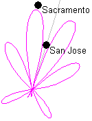 The
towers for Sacramento and San Jose are only 15 degrees apart, but the San Jose
towers are visible on the horizon.
The
towers for Sacramento and San Jose are only 15 degrees apart, but the San Jose
towers are visible on the horizon.