10/24/08
Choosing a mounting
site
Diffraction
Diffraction is the ability of a wave to bend around into the shadow formed by an obstruction. It doesn’t matter whether it is an absorbing or reflecting obstruction. Most OTA viewers depend on diffraction for their reception. The only exceptions are:
·
Where
the transmitting tower can be seen.
·
Sometimes
in cities with tall buildings reflection is more effective than diffraction.
VHF Diffraction
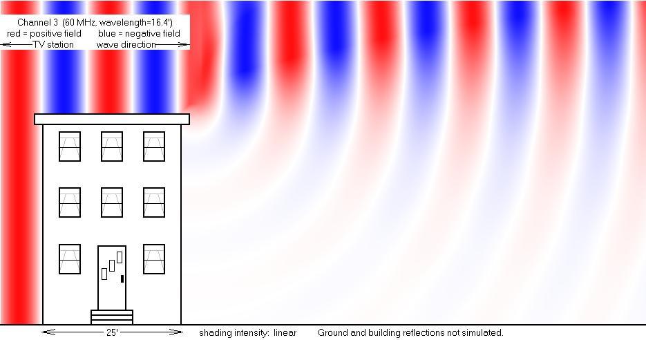
The
direction the signal is moving is always perpendicular to the wave fronts. Thus if an antenna is mounted in the shadow of
a building, the antenna should point at the top of the building, because that
is where the wave is coming from.
Low frequencies diffract efficiently, but VHF diffracts poorly. UHF is another ten times worse.
UHF Diffraction
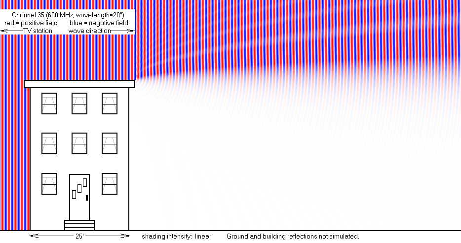
These diagrams use linear shading and thus are perhaps overly pessimistic. Reception might be possible where these diagrams show no signal. (Logarithmic shading would convey more optimism.)
TV Transmitting power allowed by
the FCC:
To make up for the inability of UHF to reach into valleys, the FCC allows UHF stations to have higher power.
Analog: DTV:
Channels 2-6 : 100 kilowatts 50 kilowatts
Channels 7-13 : 316 kilowatts 160 kilowatts
Channels 14-69 : 5 megawatts 1 megawatt
The
above numbers are approximate. The
actual power rules are more complicated than this table, and stations can argue
for and get a higher limit. But the goal
in most cases is a 60-mile reception radius.
The above power numbers are ERP numbers (effective radiated
power). ERP is defined as the
transmitter’s RF power output times the gain of the transmitting antenna. UHF transmitting antennas usually have higher
gain, so the disparity in transmitter electric bills is not as great as this
table suggests.
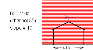
Ground reflections
Often
the signal waves are angled downward slightly, usually the result of
diffraction over an obstacle in the distance.
If there is mostly-flat ground in front of the antenna, the ground
reflection can be efficient.
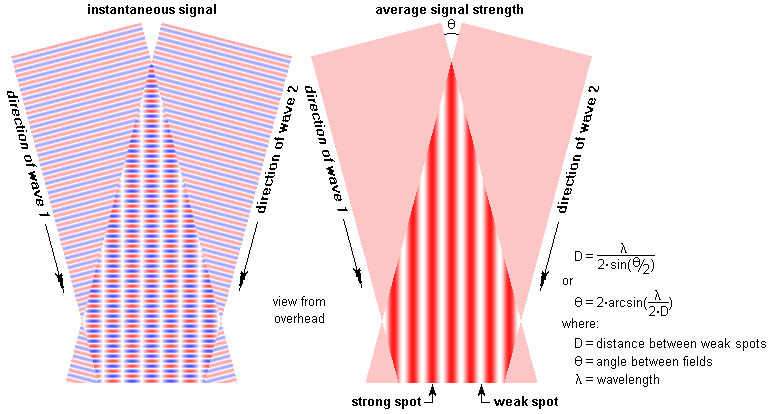
Instantaneous
voltage diagram:
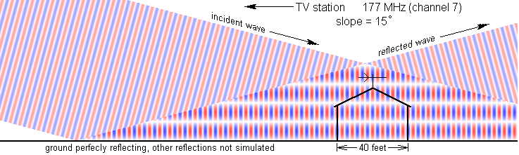
These
two waves pass through each other without affecting each other. But the antenna responds to the instantaneous
sum of the two overlapping waves. Where
the two waves subtract, there will be places where reception is very weak.
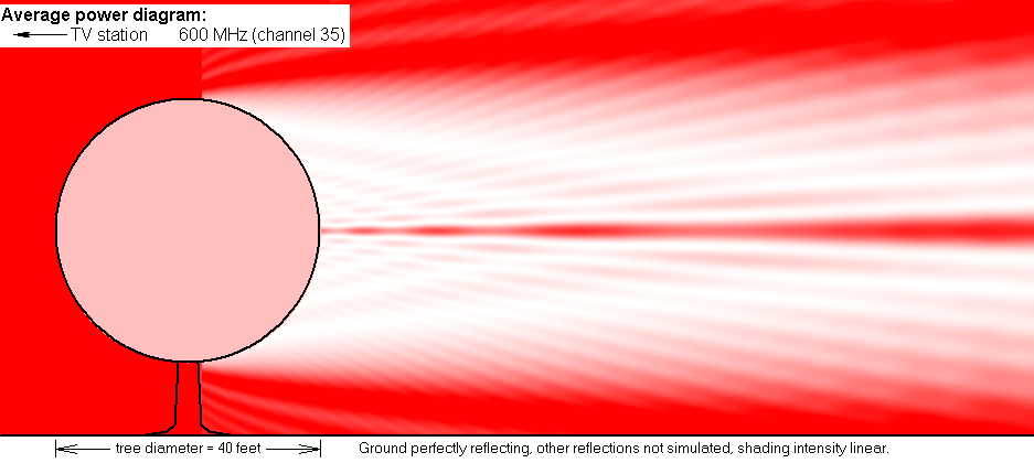
Average
power diagram:
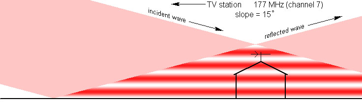
The
result is a striped region of alternating strong and weak layers parallel to
the ground. Thus there are cases where
lowering the antenna might put it in a stronger signal. So, while the following siting technique is
unorthodox, the result is very credible:
ã King Features
Syndicate. Reproduced here with
permission.
Unfortunately
a strong spot for one channel can be a weak spot for a different channel, so
compromise might be necessary.
The
ground doesn’t have to be as flat as you might guess for these layers to
form. Weeds, shrubs, and trees are
mostly transparent to VHF. A surface wet
from rain will usually be 100% reflective.
Average
power diagram for UHF:
 This layering problem is greatest for
UHF. The distance from a very strong
spot to a very weak spot can be as little as three feet. But weeds might save you. Stand where the antenna will go and look
toward the ground in the direction of the transmitter. If you see weeds or shrubs or trees, you are
OK. If you see lawn or dirt or pavement
then you likely have some layering.
This layering problem is greatest for
UHF. The distance from a very strong
spot to a very weak spot can be as little as three feet. But weeds might save you. Stand where the antenna will go and look
toward the ground in the direction of the transmitter. If you see weeds or shrubs or trees, you are
OK. If you see lawn or dirt or pavement
then you likely have some layering.
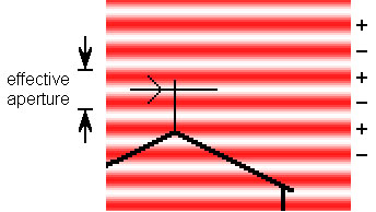 An
antenna has an aperture, over which all incoming signal is collected. In this diagram the aperture is positioned to
collect signal from two layers. But
adjacent layers always have opposite polarity, and subtract. Thus this antenna is picking up no signal at
all (assuming a 100% efficient ground reflection):
An
antenna has an aperture, over which all incoming signal is collected. In this diagram the aperture is positioned to
collect signal from two layers. But
adjacent layers always have opposite polarity, and subtract. Thus this antenna is picking up no signal at
all (assuming a 100% efficient ground reflection):
When
layering is present, if a larger antenna is necessary, choose an antenna whose
aperture is wider, not taller. Otherwise
you may find the new antenna works no better than the old one.
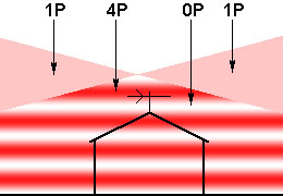 The
ground reflection can be very helpful.
Assume the power in the incident wave is P. If the reflection is 100% efficient, you might
expect the power in the overlapped area to be 2P. But instead it will vary from 0P to 4P. (Power is the square of voltage. Where the voltage doubles, the available
power goes up by 4.)
The
ground reflection can be very helpful.
Assume the power in the incident wave is P. If the reflection is 100% efficient, you might
expect the power in the overlapped area to be 2P. But instead it will vary from 0P to 4P. (Power is the square of voltage. Where the voltage doubles, the available
power goes up by 4.)
If
you can put the antenna in the most intense spot, it will collect 4 times as
much signal as with no ground reflection (assuming a 100% efficient ground
reflection).
Trees
and UHF
If a tree loses its leaves in the fall,
reception behind it will improve dramatically.
Many people get a TV for Christmas, and erect an antenna for it in
January, and then wonder why it quit working in May. It’s the trees.
In the following simulation, a tree is modeled as a perfect sphere
blocking 90% of the signal.
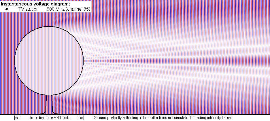
(The
simulation was in 3 dimensions. The
diagrams show the field strength in a plane through the tree center. Due to symmetry the diagrams look the same
when viewed from above. The obstruction
was coded as a disk, not a sphere, but the difference is minuscule in most
places.)
If the antenna is behind a tree, it is in overlapping fields: a
weak field that passes through the tree plus a weak field that is diffracted
around the tree. Overlapping fields are
complicated, with strong spots and weak spots.
This will be true even if the tree is not a perfect sphere. If you get a UHF antenna to work behind a
tree, you will likely see dropouts when the wind blows because the strong and
weak spots will move around as the tree deforms. Even
in a good-signal neighborhood it is inadvisable to put a UHF antenna behind a
tree.
The
farther away a tree is, the less of a problem it is. For far away trees, assume no signal
penetrates the tree, and reception will be by diffraction around the tree. Trees block 100% of satellite signals.
Trees and
VHF-high (The tree
blocks 60% of the signal.)
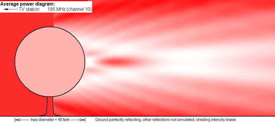
In this case the wake tendrils are very broad. The tree is not likely to deform enough to
cause a dropout. Reception might be
slightly sensitive to wind.
Trees and
VHF-low (The tree
blocks 30% of the signal. )
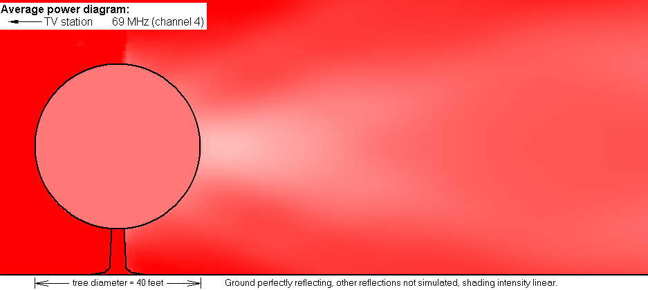
An antenna in its wake will work fine for channels 2-6.
Skyline Multi-path
The following four diagrams are identical except for the view rotation.
Rays from the transmission tower come to earth after passing over
a skyline ridge. This ridge could be a
tree line 50 yards away or a mountain ridge 5 miles away. The rays diffract at the ridge, staying in a
plane perpendicular to the ridgeline.
The result is often overlapping rays.
Overlapping fields will result in weak signal spots and strong
spots arranged in a regular pattern.
For UHF the strong and weak spots are often 5 to 20 feet
apart. If you are in a neighborhood with
overlapping fields, moving your antenna a few feet can make a huge difference
in signal strength. The chimney might
seem like the perfect site, but if the chimney is in a weak spot then the
chimney is a mistake.
To make matters worse, the pattern of strong and weak spots will be different for different frequencies. You will want to find a spot that is strong for all the channels you want. But such a spot might not exist above your roof. In this case you must search for a spot that is the best compromise for your must-have channels. In the worst case you might need two antennas and a switch.
To make matters even worse, you will not likely discover
that you are in such a neighborhood until after you have purchased and
installed the antenna. To prove that you
have strong and weak spots, you move the antenna (leftward and rightward,
higher and lower) while keeping it perfectly pointed at the signal and watching
the DTV signal strength indicator.
(What? Your TV is not on the
roof? Well maybe with some cordless
phones you can get your wife to help you.
Tape the phone to your head.) It
is hard to keep a large antenna pointed correctly while devoting half of your
attention to not falling off the roof, but a smaller antenna might not achieve
a digital lock.
At this point a professional installer starts to look like the
smart choice. But will he stick with it,
or will he too quickly declare further improvements impossible and walk
away? He will hesitate to raise his
estimate, but he will not work at a loss.
These problems are UHF problems. VHF does the same thing, but with strong and
weak spots 50 to 200 feet apart they are not very evident and there is usually
not much you can do about them.
Non-uniform fields
Overlapping fields result in non-uniform fields: layered and
continuously varying. An antenna in a
non-uniform field doesn’t perform quite like one would guess. Normally an antenna captures all the
radiation within its aperture. But in a
non-uniform field some signal gets rejected.
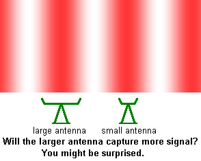 Many people in this
situation conclude they need a bigger antenna.
But a bigger aperture gathers signal from a larger area, and this larger
area is usually even more non-uniform, causing greater signal rejection. Many people have switched to a larger antenna
and found no improvement.
Many people in this
situation conclude they need a bigger antenna.
But a bigger aperture gathers signal from a larger area, and this larger
area is usually even more non-uniform, causing greater signal rejection. Many people have switched to a larger antenna
and found no improvement.
There is more than one way to explain this counter-intuitive
result. (These explanations sound
totally different, but they are equivalent.)
Probably the simplest explanation is that the antenna’s beam width gets
narrower as the aperture gets bigger.
The bigger antenna is now so directional that it cannot be pointed
directly at both sources that produce the overlapped field.
A solution to this dilemma is an asymmetric aperture. Choose an antenna whose aperture is large in
the direction of the layer, but small in the direction across the
layer. Stacked antennas will have such
an asymmetrical aperture.
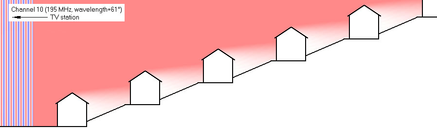
Is a higher antenna always better?
No, for the first house below:
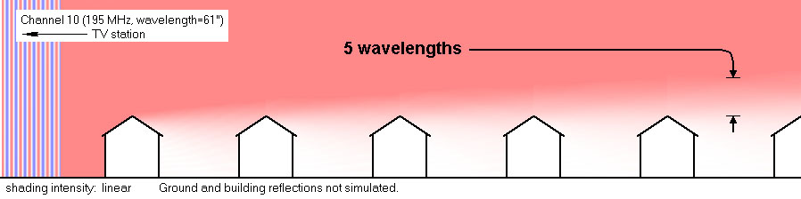
But after the signal has skimmed over several equal-height
obstacles it will be necessary to go up about 5 wavelengths to find a
full-strength signal, even if the transmitting tower can be seen from a lower
spot.
For channel 2, five wavelengths would be 86 feet. A mast that long is impractical. But below 86 feet the signal strength is
roughly proportional to the square of the height. Thus the rule of thumb: “Higher is always
better” for VHF.
For the following text, “skyline” will mean the highest
obstruction your antenna can see. The
skyline could be the top of a house or distant hill. The top of a tree could be the skyline for
UHF, but not VHF-low (for which trees are transparent).
The rules for UHF are a little more complicated than for VHF. UHF is more affected by obstructions and less affected by height. For UHF, 5 wavelengths is only about 10 feet. But a UHF antenna should be higher than this in these cases:
1. If at all possible, get
the antenna above any obstructions.
2. If your skyline is less
than 200 yards away then raising the antenna makes a significant
difference. You would be a candidate for
a tower. (When the skyline is farther than 200
yards, the benefit is usually too small to justify the effort a high mast
requires.)
You will probably want to attach a VHF antenna to your
chimney. That is also likely the best
place for a UHF antenna. But if your
chimney mount is still obstructed (by trees, etc.) then an unobstructed site
closer to the ground will work better for UHF. The essential
goal is to find a spot where your UHF antenna can
see a distant skyline in the direction of the station.
Note
that on the front of a hill, the antenna height often makes little or no
difference (VHF and UHF):
Power lines
Power lines will reflect the signal. But that is just one reason to keep antennas
away from power lines. If there is RF
noise in the power lines, the lines will transmit the noise to a close antenna.
Many people have been killed when their antenna fell into power
lines. Channel Master recommends that
the antenna be kept away from power lines by a distance of twice the mast
length plus twice the antenna length.
Attic antennas
If an indoor antenna is not as reliable as you want, an attic
antenna is the next step up. If you are in
a neighborhood with moderately strong signals, an attic antenna might
work. But you are wasting your time
installing an attic antenna in a poor-signal neighborhood. Most successful attic antennas are within 20
miles of the transmitter. (30 miles often works if you are on a
hillcrest.) The problems with attic
antennas are:
- The antenna might not be high
enough above obstacles outside the house such as trees.
- It is hard to estimate the signal
loss caused by the wood and other construction materials.
- Metal objects in the attic can
block the signal.
Estimating
the signal loss in ordinary construction materials requires knowledge of their
water content. Exceptions are aluminum
siding, stucco (which has an embedded metal screen), and foil-backed
insulation, all of which totally block all signals. Concrete and most bricks have moderate water
content, but their thickness is enough to block all signals. In a desert, plywood becomes so dry that it
causes no signal loss at all, even for UHF.
In any other place, there will be some moisture. Exterior wood is generally always wet inside,
especially in north facing surfaces.
(Paint does not prevent this.)
The amount of water varies with the weather. Dry asphalt shingles are mostly transparent
to TV signals, but the way they overlap encourages water to persist between
them. The vapor barrier is often wet on
one side or the other. The bottom line
is that there is no way to predict the signal loss in these materials. It is usually a mistake to point an antenna through
a surface that gets totally wet in rain.
Metals
reflect signals. A metal object 8 inches
long is big enough to reflect UHF.
Smaller objects, such as nails, are of no concern. Wires and metal pipes effectively reflect
VHF, as do plastic pipes containing water.
If these reflecting objects are positioned to the side, to the rear,
above, or below the antenna, they will have little effect on it, provided they
are not too close. These objects should
be further away than 2 feet for UHF, 4 feet for VHF-high, or 6 feet for
VHF-low, and an even larger separation will help a little. (Some might wonder why these numbers are not
proportional to the wavelength. It is
because the lower frequency antennas are lower in gain. An antenna’s aperture depends on the gain as
well as the wavelength.)
There should be no horizontal or diagonal wires or pipes in front of
the antenna. A perfectly vertical metal vent pipe is
invisible to TV signals, but its flashing at the roofline might not be.
Inner-city antennas
In good-signal
areas, small low-gain antennas may work fine.
Indoor antennas nearly always work up to 10 miles from the
transmitter. They often work up to 20
miles for people who live on hillcrests, and sometimes 30 miles if the
transmitting tower is visible. But if http://www.antennaweb.org says you are
not a candidate for an indoor antenna then don’t waste your time and money on
this.
If
you are in a city and the transmitters are all around you, you might get tired
of getting up to re-aim the antenna when you change channels. In that case, an omni-directional
antenna, like a disk antenna, mounted in your attic might serve you well. But an omni-directional antenna will not work
for DTV in a multi-path situation.
Multi-path in cities occurs mostly when there is a big building blocking
the direct path to a TV tower. If you
see ghosting on some of your analog channels then you are probably not a
candidate for an omni-directional antenna.
See Omni-directional
antennas.
Common misconceptions (optional reading)
What about reflections?
Many websites say
ghosts are caused by reflections off nearby objects. But this is true maybe 1% of the time. Most such reflections are spherical waves
that die off quickly due to spreading, too quickly to be delayed enough to
produce a ghost. Only a plane surface
can produce a reflection that will persist long enough, and most natural flat
surfaces are at an angle that will reflect upwards away from any antenna. Building surfaces can produce ghosts. But like for a mirror, the reflection off a
building surface is very directional.
What about front-to-back ratio?
Many websites say a
high front/back ratio will block ghosts that arrive from the rear. But ghosts normally come from the front and
are caused by the most direct path being blocked.
Conceivably an
obstruction could be just high enough to block the antenna but not high enough
to block the signal reflecting off a building to the rear. But the blockage will necessitate a high gain
antenna, and all such antennas have a high front/back ratio. So again the front/back ratio is something
that never has to be considered. See Front/back ratio.
Related
topics
Fading (Why a signal drops out for no apparent
reason)
Field strength
meters (for finding the strongest
spots)
Multi-path
interference (There are two kinds)
Painting an
antenna (Is this OK?)
This page is part of “An HDTV Primer”, which
starts at www.hdtvprimer.com