7/25/08
Common TV Antenna
Types
![]()
Shown above
is the radiation diagram for a 9-element Yagi antenna that the author once used
to receive channel 12. To interpret this
diagram, imagine that the antenna is at the origin. The length of a line from the origin to any
point on the surface is proportional to the gain in that direction.
HDTV Antennas
An antenna
made for analog TV will work fine for DTV.
There is nothing different about an antenna for DTV or HDTV. Unscrupulous people have labeled their antennas
“HDTV Antennas” as a marketing ploy. The
honest antenna makers have had to re-label their products likewise to avoid
losing sales.
Some terms
Gain – a measure of how much signal the antenna will collect.
Beam width – how directional an antenna is.
Bandwidth – how the gain varies with
frequency. A narrowband antenna will
receive some channels well, but other channels poorly.
This is an easy page. But if you want, you can skip or skim the rest of this page without compromising your understanding of the pages that follow.
The Dipole
This is the
simplest TV antenna. Variations on the
dipole are the bowtie (which has wider bandwidth), the folded-dipole (which can
solve an efficiency problem) and the loop (a variation on the folded dipole). All four have the same gain and the same
radiation field: a torroid (doughnut shape).
The gain is generally 2.15 dBi.
“dBi” means “dB of improvement over an isotropic radiator”, which
is an antenna that radiates equally in all directions. This sounds like a discussion of transmitting
antennas, and it could be. An antenna
will have the same gain when receiving as when transmitting, and also the same
radiation pattern.
The dipole
has positive gain because it does not radiate equally in all directions. This is a universal truth. To get more gain, an antenna must radiate in
fewer directions. Imagine a spherical
balloon. Now press on it from opposite
sides with a finger of each hand. Push
in until your fingers meet. The result
looks like the torroid above. But more
importantly, the balloon expanded in the other directions. A-hah! Gain!
That’s the way antennas work.
Keep this
balloon analogy in mind. More
complicated antennas work by reducing radiation in most directions. They distort the balloon considerably, but
the volume of the balloon remains constant.
Another
rating system for antennas uses dBd, which means dB of improvement over
a dipole antenna. To convert dBd to dBi,
just add 2.15. Antenna makers specify
their gains in dB. They actually mean
dBd, but given the way they exaggerate their claims, dBi is usually closer to
the truth.
In the US, TV
antennas are always horizontal. If you
rotate an antenna about the forward axis (a line from the transmitting antenna)
the signal strength will vary as the cosine of the angle. In other words, when the antenna elements are
vertical, no signal is received because TV signals have horizontal
polarization.
Stacked Dipoles
Two heads are
better than one, and so it is with dipoles.
N dipoles will take in N times as much RF power as one dipole, provided
they are not too close to each other.
Thus a 4-dipole antenna would have a gain of 8.15 dBi. (That is 2.15 dBi doubled once (plus 3 dB)
and doubled again (plus another 3 dB).)
This assumes their positions and cable lengths are adjusted so that
their signals add in-phase. This
explanation of gain may seem at odds with the balloon explanation, but
ultimately they are equivalent. (Adding
dipoles does not increase the volume of the balloon because phase cancellation
occurs in some directions.)
Dipoles are
commonly stacked horizontally (collinearly), vertically (broadside), and in
echelon (end-fire).
When dipoles
are stacked horizontally, the horizontal beam width becomes very narrow. This is because they do not add in-phase for
directions not straight ahead.
Similarly, when stacked vertically, the vertical beam width becomes
narrower.
Lets say you
are 20 miles from a city and TV transmitters are scattered all over the
city. A medium gain antenna might be too
weak, but a high gain antenna would be so directional you would need a rotor. Solution:
A bunch of dipoles stacked vertically would give you the gain you
need. The vertical narrowness of the
resulting beam is of little importance, but the horizontal broadness of the
beam means no rotor needed.
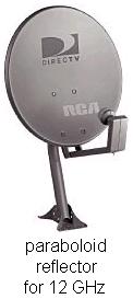
Reflector Antennas
Radio waves
will reflect off of a large conducting plane as if it was a mirror. A coarse screen works just as as well. Reflector antennas are very common.
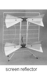
The double
bow-tie above has an average gain of 6 dBi.
With a bigger screen it would have more.
The parabolic reflector focuses the signal onto a single dipole, but its
bandwidth is a little disappointing. The
corner reflector has a little less gain but much greater bandwidth. The corner reflector has roughly the gain of
three dipoles. It is a good medium gain
antenna, widely used for UHF. If you
need more than 25 dBi then the paraboloid dish is the only practical choice,
but they are huge.
Log-Periodic Dipole Arrays (LPDA)
The LPDA has
several dipoles arranged in echelon and criss-cross fed from the front. The name comes from the geometric growth,
which is logarithmic.
This is a
very wideband antenna with a gain of up to about 7 dBi. For any frequency, only about three of the
elements are carrying much current. The
other elements are inactive. As
frequency increases, the active elements “move” toward the front of the array. Most VHF TV antennas are LPDAs.
TV LPDAs come
in two types: straight and Vee. The Vee
type (LPVA) has a very slightly higher gain for channels 7-13. But this author often favors the straight
type since it has nulls 90°
to each side that can be used to cancel out interference.
Yagi Antennas
A Yagi
antenna has several elements arranged in echelon. They are connected together by a long
element, called the boom. The
boom carries no current. If the boom is
an insulator, the antenna works the same.
The rear-most
element is called the reflector.
The next element is called the driven element. All the remaining elements are called directors. The directors are about 5% shorter than the
driven element. The reflector is about
5% longer than the driven element. The
driven element is usually a folded dipole or a loop. It is the only element connected to the
cable. Yet the other elements carry
almost as much current.
The Yagi is
the most magical of all antennas. The
more directors you add, the higher the gain becomes. Gains above 20 dBi are possible. But the Yagi is a narrowband antenna, often
intended for a single frequency. As
frequency increases above the design frequency, the gain declines
abruptly. Below the design frequency,
the gain falls off more gradually. When
a Yagi is to cover a band of frequencies, it must be designed for the highest
frequency of the band.
An antenna
has an aperture area, from which it captures all incoming radiation. The aperture of a Yagi is round and its area
is proportional to the gain. As the
leading elements absorb power, diffraction bends the adjacent rays in toward
the antenna.
The formula
for the aperture area of any TV antenna is
A=Gl2/4p
where l is the
wavelength and G is the gain factor over an isotropic antenna (not dB).
Nonessential reading:
Question: How does the energy collected by the
directors get to the cable?
Answer: It is re-radiated to the driven element as
normal radio waves.
Question: Why don’t the re-radiated waves go backward
or laterally?
Answer: Because all the directors cancel each other
in those directions.
Question: Why don’t these re-radiated waves prevent the
diffraction of incident waves inward toward the boom?
Answer: Because the phase of the re-radiated waves has
been changed by about 90 degrees, so they neither subtract nor add to the
incident waves.
Question: How did the director currents get changed by
90 degrees?
Short
answer: The element lengths control this. The director currents are shifted -90 degrees
while the reflector current is shifted +90 degrees.
Long
answer: This graph shows how the current induced in a
rod is affected by the length of the rod.
The phase changes quickly with a small change in element length.
The current in the metal rod can be
thought of as a standing wave: a signal bouncing back and forth in the rod
until it dies out, meanwhile getting reinforced by incoming energy. If the rod is too long, the bouncing signal
quickly falls behind the incoming signal.
When it gets more than 90 degrees behind, it subtracts from the incoming
signal. A rod too short is a similar
case.
The bandwidth
of a Yagi can be increased by sizing the reflector for the lowest frequency of
the band while sizing the directors for the highest. But this decreases the best gain of the
antenna. (It is said that the
gain-bandwidth product remains the same.)
A better way to increase the bandwidth is to replace the reflector
element with a corner-reflector assembly.
This boosts
the performance on the lower numbered channels without hurting the high
channels. Although the
Yagi/Corner-Reflector might not be the best antenna, it is the most common UHF
TV antenna, mainly because it can be mounted on the front of a VHF antenna
without degrading the VHF antenna.
Comparing a Yagi/Corner-Reflector to an 8-Dipole-Reflector
The graph
above shows the gain functions for four TV antennas:
- Plot A is the Channel Master 4228
8-Bay, a stacked dipole reflector antenna.
- Plot B is the Channel Master 4248,
a Yagi/Corner-Reflector.
- Plot C is the 4248 with all of
its directors removed, making it a pure corner reflector antenna.
- Plot D is the 4248 with its
corner reflector removed and replaced by a single reflector element,
making it a standard Yagi. The D2
plot shows the backward gain where this exceeds the forward gain.
The point of
this graph is that a Yagi/Corner-Reflector performs like a Yagi for the high
numbered channels and a corner reflector for the low numbered channels. For the middle channels it outperforms the
sum of the two types.
A UHF Yagi
today is designed for channel 69. If you
see an old Yagi, it might be intended for channel 82. In the future they will be cut for channel
51. It is not possible to tell by
looking at a Yagi which era it belongs to, so be careful.
Radiation patterns
As you can
see, the 8-Bay is a very directional antenna.
If miss-aimed by 5°
you can lose 1 dB of signal. If the
skyline is more than 5°
above horizontal, you should tilt the antenna up to point at the skline.
The overhead
view shows nulls at 30°
and 90° to both
sides. These can be used to eliminate
multi-path (ghosts) or interference. You
simply rotate the antenna until the offending signal is in one of the nulls.
____________________________________________________________
A Yagi also
has some forward nulls that can be used as ghost killers. But a Yagi/Corner-Reflector acts more like a
corner reflector for most channels, and has no nulls. At channel 60 you can finally see the Yagi
pattern start to emerge.
This author
prefers the 8-Bay over the Yagi/Corner-Reflector because
- It has high gain.
- Its gain is evenly distributed
over the channels.
- It has nulls that can eliminate
multi-path.
- It has a rectangular aperture
that permits efficient stacking when more than 8 bays are necessary.
But the high
gain means it is hard to aim. In
good-signal areas, avoid high gain antennas.
Related topics
Beam width (a formula relating beam width to gain)
Front-to-back ratio (Is this number important?)
Capacitive
hats (an uncommon solution)
Antenna
elements (how many?)
Gamma match (no balun required)
Guy wires (effect on antenna)
Dish antennas (for satellite reception)
FM antennas (Will a TV antenna work?)
Log-Yag
antennas (a common hybrid)
Omni-directional
antennas (common disk antennas)
This page is part of “An HDTV Primer”, which
starts at www.hdtvprimer.com