10/7/08
Shown
above is the 3-dimensional radiation diagram for a 9-element Yagi antenna that
the author once used to receive channel 12.
To interpret this diagram, imagine that the antenna is at the
origin. The length of a line from the
origin to any point on the surface is proportional to the gain in that
direction.
2-dimensional
pattern diagrams are more common. The
following two diagrams describe a Channel Master 4228.
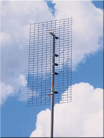
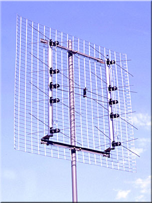
Reflector
antenna -
Radio waves will reflect off of a large conducting plane as if it was a
mirror. A coarse screen will work just as
well. The reflector eliminates most
reception from the rear while at least doubling the forward gain. Reflector antennas are very common.
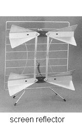
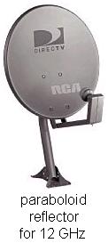
The
screen reflector shown above has the gain of about 4 dipoles. The parabolic reflector focuses the signal
onto a single dipole, but its bandwidth is a little disappointing. The corner reflector has a little less gain
but much greater bandwidth. The corner
reflector has roughly the gain of three dipoles. It is a good medium gain antenna, widely used
for UHF. If you need more than 25 dBi
then the paraboloid dish is the only practical choice, but for VHF or UHF they
are huge.
RFI (Radio Frequency
Interference) (see interference)
Rotors (antenna rotators, motorized
antenna aimers) - When
a highly directional antenna is employed, a rotor becomes necessary when the
desired stations are in multiple directions.
A
rotor is a minor nuisance for analog stations, but it becomes a major problem
for digital stations. This is because it
takes 10 times longer to discover the correct aim for a DTV station. (Instead of simply looking at the level of
snow, you must count the dropouts that occur over a half-minute period, then
re-aim and try again.) The author
discovered that for weak stations it took him 5 to 10 minutes to achieve the
optimum aim, and during that time he missed about half the program dialog. Because of this he quit using that antenna.
For
an ideal rotor, the antenna would always point where the indoor controller
indicated. But the Radio Shack rotor the
author was using suffered “creep”, a small directional error accumulation. The creep would build up fastest during the
short jerky movements typical during station searches, and soon the antenna
would be pointing far from where the dial said, making the dial calibrations
useless.
The
author later switched to the Channel Master rotor that has an infrared remote
control. This rotor doesn’t seem to
suffer as much creep, but then, this antenna isn’t used very often. But it can creep. The controller has a microprocessor that
counts the number of times the rotor is used.
After a certain number, the controller will recalibrate to eliminate the
accumulated creep. It does this by
rotating the antenna to the limit in one direction, then to the limit in the
opposite direction, and then to the requested channel direction. If you must have a rotor, get one like this
(or one that doesn’t creep in the first place).
If
you like TiVo then you will not want a rotor.
TiVo-like recorders can’t make antenna adjustments.
This
author recommends that if your stations are in just two directions, you will be
happier with two antennas. A common splitter
can be used to combine the two antennas.
Doing this will cost you a lot of signal strength (Half of the signal
from each antenna gets rebroadcast out the other antenna. Figure a 3.5dB loss at the splitter.). A Join-Tenna is a device that can avoid this
loss.
Another
way to avoid the 3.5 dB loss is to use an antenna switch to combine the two
antennas. The author likes the Radio
Shack 15-1968 switch, which has an infrared remote control. But again, the TiVo can’t work the switch.
Servo motor
- This is a small motor in a
C-band dish feed assembly. This motor
selects whether vertical or horizontal polarization is to be received.
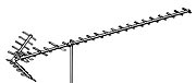
Single channel Yagi
- The ultimate antenna for VHF is
a single channel Yagi. No other type has
as much gain. But these are large
antennas, and they work well for only one channel, so these are desperation
antennas. Reasonably priced single
channel Yagis are available from Wade.
See “Stores and websites supplying antenna equipment ”. See http://www.wade-antenna.com/Wade/cutchannel.pdf
on the Wade website. See also
Join-Tenna.
S/N (Signal to Noise Ratio)
- Whether a signal is receivable
is determined by the signal to noise ratio.
Noise management is discussed at http://www.hdtvprimer.com/ANTENNAS/basics.html
. If you do not manage the noise
properly, you might be throwing away a sizable portion of the antenna signal.
Splitters/Combiners/Diplexers
- A splitter is a sort of “Y-adapter”.
All splitters are bi-directional, and thus will serve also as
combiners. These devices are usually
85%-95% efficient, whether used as splitters or combiners. There are four basic types. They look almost identical, but are very
different devices.
50MHz-900MHz
splitter/combiner -
Commonly available in 2-way, 3-way, 4-way, and 8-way types, this is the
splitter you want if you have multiple TVs or want to gang two identical
antennas. The splitter is designed so
that it will not cause reflections, but if you leave an output unconnected then
there will be reflections. (See
Terminators.) If a 2-way splitter were
100% efficient, you would figure a 3dB loss since each TV would get half the
power. Some splitters incorporate a DC
Block in one output so that the splitter can be between an amplifier and its
power injector. (See DC Block, Antenna
amplifiers)
900MHz-2200MHz
splitter/combiner -
These can be used with satellite systems, but be sure you know how
control issues will be resolved.
VHF/UHF
splitter/combiner - This
device will split UHF off from the VHF, which would be necessary for TVs with
separate VHF and UHF inputs. The device
will also combine a VHF antenna with a UHF antenna. The advantage of this splitter is that there
is no 3dB loss. (Technically, this
device should be called a diplexer.)
Satellite/OTA
diplexer - This
device will allow a satellite dish and an over-the-air antenna to share the
same cable. The loss in the device will
not be 3dB, but there will be some small loss.
Check for whether DC is blocked to the OTA port. Satellite/OTA diplexers will not work with
the new 5-LNB dishes from DirecTV.
Note: Splitters in cable systems with “on demand”
features must pass 5MHz-900MHz.
Stacked antennas
- The use of multiple antennas is
called stacking or ganging.
The antennas must be identical.
Dipoles
are commonly stacked horizontally (collinearly), vertically (broadside), and in
echelon (end-fire).
When dipoles are stacked horizontally, the horizontal
beam-width becomes very narrow. This is
because they do not add in-phase for directions not straight ahead. Similarly, when stacked vertically, the
vertical beam-width becomes narrower.
The
same principles apply when stacking whole antennas, not just dipoles. See “The two antenna trick” at http://www.hdtvprimer.com/ANTENNAS/silver.html
.
Standing waves, SWR
- If a transmission line ends in nothing
(either an open or a short), 100% of the signal gets reflected back toward the
source. The forward moving signal and
the backward moving signal pass through each other without affecting each
other. But at each point in the line the
two signal voltages add together, and considering phase, some places they will
subtract. The result is a stationary
voltage pattern, called a standing wave, arrayed along the transmission line.
If
an incomplete load (something other than 75 ohms) causes less than a 100%
reflection, then the standing wave pattern doesn’t show complete
cancellation. The ratio of the highest
and lowest voltages that can be found along the line is called the Standing
Wave Ratio (SWR).
SWR=Vmax/Vmin
An
SWR of 1 is good: There is no reflected
signal.
An
SWR of infinity is bad: There is total
reflection.
An
SWR of 1.5 is not too bad.
There
are formulas that will predict the SWR if the load impedance is known.
(Since the TV impedance equals the
transmission line impedance, there is normally no standing wave. But there is a matching loss where the antenna
connects to the line. This loss
numerically equals the SWR loss that would occur if the antenna were used for
transmitting. So the antenna’s SWR is
very useful even though it is seemingly inappropriate.)
Stores and websites supplying antenna
equipment - None
of the vendors listed here has contributed financially or materially to this
website or this author.
The
following manufacturers’ websites have store locators:
·
Channel
Master ( www.channelmaster.com
) (Fry’s is usually poorly stocked)
·
Winegard
( www.winegard.com )
·
Antennacraft
( http://www.antennacraft.net )
·
Wade
(formerly Jerrold) ( www.wade-antenna.com
) **
·
Radio
Shack ( www.radioshack.com )
The
following manufacturers sell online:
·
Antennasdirect.com ( www.antennasdirect.com
) A.k.a. Terrestrial Digital
·
Radio
Shack ( www.radioshack.com )
Manufacturers
to avoid:
·
Terk
– Severe hype. The equipment works, but Terk marketing prevents intelligent decision-making.
·
Xium
– Totally fraudulent antennas
Online
stores:
·
Warren
Electronics ( www.warrenelectronics.com
) (Channel Master, Winegard, Antennacraft)
·
Stark
Electronics ( www.starkelectronic.com ) (Channel
Master, Winegard, Antennacraft, Blonder Tongue*)
·
SummitSource.com
( www.summitsource.com ) (Winegard, Antennacraft, Channel Master)
·
SolidSignal.com
( www.solidsignal.com ) (Channel
Master, Winegard, Antennacraft, Blonder Tongue*, AntennasDirect)
·
TV
Antenna Source (www.dennysantennaservice.com)
(Winegard. This small outfit is
especially friendly.)
* Blonder Tongue makes CATV antennas, which are slightly
more rugged and more expensive than consumer grade antennas.
** Wade is presently the only maker of inexpensive VHF
single channel Yagis. Wade sells only
through distributors, but the distributors don’t stock much. Lafayette Electronics will ship you one UPS (Email Betty at sales@lafayetteelectronicsupply.com ).
Otherwise you must go to the Wade website, find your local distributor,
call him and order the antenna, and the antenna will be shipped out of
Ontario. Assume 2 weeks. You will probably have to drive to the store
to pick it up. While Wade sells full
lines of TV antennas for CATV and consumers, other vendors are easier to deal
with.
Terminators
for 75-ohm lines - A
75-ohm transmission line must end in a load resistance equal to 75 ohms or much
of the signal will be reflected backwards, possibly getting retransmitted out
the antenna. Signals can literally
bounce back and forth inside transmission lines. All TVs and amplifiers have 75-ohm inputs, so
normally there is no problem.
If
you use a splitter but forget to connect one output to anything, some of the
signal will be reflected back towards the antenna. Viewers of the connected TV might discover
some stations seem to be missing. The
reflected signals can increase the likelihood that the amplifiers will
overload. These problems can be
insignificant, or they can be more confusing than significant. Getting 75-ohm terminators and connecting
them to the unused outputs of the splitter will stop the reflections.
Tilt angle - If the skyline
(including the tree tops) is a few degrees above horizontal, you will benefit
from tilting the antenna up to point at the skyline, although for low-gain
antennas this benefit is insignificant.
If
your visible skyline is many miles away, this signal might arrive at different
elevation angles on different days. Some
authors will recommend a tilt motor so that you can always maximize your signal
strength. But this author believes that
high-angle days are always strong signal days and the minor improvement in
tilting the antenna up is not necessary.
This author recommends a tilt motor only when a rotor is employed and
the skyline angle is different in different directions.
Transmission lines - The common types are coaxial cable, twin-lead,
twisted-pair, wave-guide, and strip-line (PC etch). Although lamp cord can be used for
transmission line, it has some problems.
Coaxial cable is recommended for all TV
systems. Twin-lead (ribbon cable) used
to be common for TV antennas. It has its
advantages. But due to its
unpredictability when positioned near metal or dielectric objects, it has
fallen out of favor. (Such objects, even
if not touching the cable, cause a portion of the signal to bounce, return to
the antenna, and get retransmitted.)
All
high frequency transmission lines have a property called characteristic
impedance. Twin-lead is usually 300
ohms, while coaxial cable for TVs should always be 75 ohms. (50-ohm coaxial cable is also common. Avoid that cable.) Although rated in ohms, this has nothing to
do with resistance. A resistor converts
electric energy into heat. The “75 ohms”
of a coaxial cable does not cause heat.
A transmission line must end in a load resistance equal to the line’s
characteristic impedance in order to prevent signal reflections in the cable.
But
coax also has ordinary resistance (mostly in the center conductor) and thus
loses some of the signal, converting it into heat. The amount of this dissipation (loss) depends
on the frequency as well as the cable length.
Trees as obstructions
- A tree has very little effect
on VHF-low, but a significant effect on VHF-high. But the big problem is UHF. A tree with leaves blocks about 90% of a UHF
signal. The space behind the tree is an
overlap of the signal going through the tree and the signal diffracting around
the tree. Such overlapping fields have
an alternating pattern of strong and weak spots separated by only a few
feet. An antenna in a strong spot might
work nicely until the wind blows, deforming the tree and moving the spots. Thus, for DTV stations, you are likely to see
dropouts when the wind blows. Even in a
good-signal neighborhood it is inadvisable to put a UHF antenna behind a tree.
If the tree loses
its leaves in the fall, reception behind it will improve dramatically. Many people get a TV for Christmas, and erect
an antenna for it in January, and then wonder why it quit working in May. It’s the trees.
The
farther away a tree is, the less of a problem it is. For far away trees, assume no signal
penetrates the tree, and reception will be by diffraction around the tree. See Diffraction.
Trees
block 100% of satellite signals.
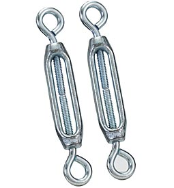
Turnbuckle
- This is a device for tightening
guy wires. Since one side has
left-handed threads, a turnbuckle will tighten the guy wire without twisting
it. For the type pictured below, you
must tape over the turnbuckle after adjusting it or vibration will cause it to
loosen with time.
Twin-lead transmission line (ribbon
cable) -
Twin-lead used to be common for TV antennas. It has its advantages. But due to its unpredictability when
positioned near metal or dielectric objects, it has fallen out of favor. (Such objects, even if not touching the cable,
cause a portion of the signal to bounce, return to the antenna, and get
retransmitted.)
For
UHF, twin-lead should be kept at least an inch away from anything metal, and
should not be allowed to touch anything dielectric (plastic).
For
VHF, the twinlead should not be allowed to touch anything metal, even if
insulated, and should not lie against anything dielectric.
UHF - The Ultra High Frequency spectrum is
everything from 300 megahertz to 3.0 gigahertz.
One of the bands within this spectrum is the TV UHF band, which goes
from 470 megahertz (channel 14) to 806 megahertz (channel 69). Each of these stations occupies 6 megahertz
of that spectrum.
Velocity factor
- Signals travel at the speed of
light. However the speed of light inside
a transmission line is slightly slower than the speed of light in a
vacuum. It depends on the dielectric
constant of the material holding the electric and magnetic fields.
Most
transmission lines employ polyethylene (PE) or a PE-air mixture. The speed of light in PE is 66% of the speed
of light in a vacuum. The speed of light
in air is about 100% that of a vacuum. A
coaxial cable with solid PE between the conductors will have a velocity factor
of 0.66.
For
twin-lead, the electric and magnetic fields are partly in the PE and partly in
the air around the twin-lead. As a
result, the velocity factor is somewhere between 0.66 and 1.00, usually around
0.90.
PE
is somewhat lossy at high frequencies.
To reduce the loss, microscopic air bubbles (foam) are often blown into
the PE of coaxial cables. This also
raises the velocity factor to 0.75 or 0.85, but it makes the cable less rugged.
The
velocity factor is usually of no use to Average Joe installing a TV
antenna. In the rare cases where the
transmission delay is important, the velocity factor becomes important.
Vertical antennas
- There are countries where TV
signals have vertical polarization, but not in North America. U.S. TV stations are allowed circular or elliptical
polarization if they want. But fewer
than 10% of U.S. stations do this. Most
stations figure the vertical component of circular polarization is wasted
power. See Polarization.
If a
local TV station uses circular or elliptical polarization then you can probably
receive it reliably using either a vertical or a horizontal antenna. A vertical antenna can be a good choice if
you want TV reception in a moving vehicle.
The
common vertical antennas are the vertical dipole and the ground plane
antenna. Three common versions of
the ground plane antenna are:
1.
A
quarter-wave vertical whip with 3 or 4 horizontal ground plane “radials”. This is a small version of the popular CB
antenna.
2.
A
quarter-wave vertical whip that uses the metal roof or trunk lid as the ground
plane.
3.
A
¾-wave vertical whip with a coil in the middle.
This is a scaled-up version of a popular cell phone antenna.
VHF - The Very High Frequency spectrum is
everything from 30 megahertz to 300 megahertz.
It is divided into many bands for different purposes (police, fire, aircraft,
etc.) Two of the bands within VHF are:
1.
The
TV VHF-low band. This band goes from 54
megahertz (channel 2) to 88 megahertz (channel 6).
2.
The
TV VHF-high band. This band goes from
174 megahertz (channel 7) to 216 megahertz (channel 13)
Each channel occupies 6 megahertz of
this spectrum. (There is a 4 MHz gap
between channels 4 and 5.)
Watt, Kilowatt, Megawatt
- A watt is a unit of measure
that tells the rate at which energy is produced or consumed. A kilowatt is a thousand watts. A megawatt is a million watts. One watt is one joule per second. 745.7 watts is one horsepower.
Wavelength - For every frequency there is a
wavelength. They are related by the
formula f=300/l where:
f is the
frequency in megahertz.
l is the wavelength
in meters.
Antenna
elements are typically about a half wavelength long.
Yagi antenna
- A Yagi antenna has several
elements arranged in echelon. They are
connected together by a long element, called the boom. The boom carries no current. If the boom is an insulator, the antenna
works the same. The rear-most element is called the reflector. The next element is called the driven
element. All the remaining elements
are called directors.
The
directors are about 5% shorter than the driven element. The reflector is about 5% longer than the
driven element. The driven element is
usually a folded dipole or a loop. It is
the only element connected to the cable.
Yet the other elements carry almost as much current. The more directors you add, the higher the
gain becomes. Gains above 20 dBi are
possible. But the Yagi is a narrowband
antenna, often intended for a single frequency.
Yagi antennas are described in more detail at http://www.hdtvprimer.com/ANTENNAS/types.html
.
Yagi/Corner-reflector
antenna - This
antenna is a hybrid between a Yagi and a corner reflector antenna. The directors determine the gain on the high
channels, while the size of the corner reflector determines the gain on the low
channels. It attempts to be a wideband
antenna, but in fact it does a mediocre job on the low channels. Although the Yagi/Corner-Reflector is not the
best antenna, it is the most common UHF TV antenna, mainly because it can be
mounted on the front of a VHF antenna without degrading the VHF antenna.
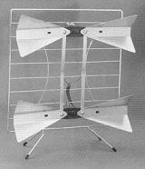
2-Bay antenna
- This is a two dipole reflector
antenna. It is UHF only. An indoor version is called the “Double
Bow”. It has some flaws (a ribbon cable,
poor matching on the low channels) and yet is still one of the better indoor
antennas.
Excellent
outdoor 2-bays are now available: the DB-2 by antennasdirect.com and the 4220
by Channel Master. They are small enough
to use indoors, and as such are presently the highest performing indoor
antennas available.
4-Bay antenna
- This is a stacked dipole
reflector antenna. It has a fan-shaped
beam: very broad horizontally, very narrow vertically. An excellent antenna in the 20-30 mile range,
a rotor is usually not needed. It is a
bad choice where multi-path occurs.
(Multi-path and ghosting result when the direct signal path is blocked.) 4-Bays are made by Channel Master, Winegard,
Antennacraft, Wade, and Antennasdirect.com .
This UHF only antenna is roughly 40”x18”.
 Channel Master
4-Bay
Channel Master
4-Bay
4DTV - This is a digital satellite subscription
service requiring an 8-foot motorized C-band dish. About 10 HD channels and 150 CD-quality SD
channels are available.
8-Bay antenna
- This is a stacked dipole
reflector antenna. Its searchlight-like
beam makes it very different from the 4-Bay.
This highly directional high gain antenna is commonly thought to be the
strongest overall UHF antenna. 8-Bays
are made by Channel Master, Winegard, and Antennasdirect.com . The Winegard 8-Bay is skewed in favor of the
low channels, and is presently the best antenna available for channels
14-30. (If you want an antenna skewed in
favor of the high channels, select a big Yagi/Corner-reflector.) 8-Bays are roughly 40”x36”. 8-bays are intended only for UHF. However the Channel Master 8-bay will pick up
channels 7-13 quite well.
 Channel master
8-Bay
Channel master
8-Bay
This page is part of “An HDTV Primer”, which
starts at www.hdtvprimer.com