9/2/08
Actuator - This is another name for the stepper
motor of a C-band dish. This motor moves
the dish to different satellites.
Adjacent channel interference
- When the station you want is
not receivable because of a much more powerful station in the next channel
above or below, you have adjacent channel interference.
Before
1998, the FCC would never allow stations in the same city to occupy adjacent
channels. (There were exceptions for
channels 4-5, 6-7, and 13-14 because gaps exist between those channel
pairs.) But due to improved receiver
technology, the FCC now allows any channel assignment.
When
a signal is 10 to 15 times more powerful than that of an adjacent channel
station, most receivers become unable to receive the weaker station. To receive a far away station, you might need
to use a directional antenna to reduce the strength of a nearby adjacent
channel station. See “Nulls in radiation
pattern”. But if both stations are in
the exact same direction you might be out of luck. There are some frequency selective filters
that can “trap” out a channel, but they are seldom able to reduce an adjacent
channel by more than half. (e.g.
Winegard UT-2700 Dual Trap)
When
adjacent channel stations broadcast from the same tower or adjacent towers they
must have an agreement that neither will exceed 10 times the other’s power.
Antenna - A device for converting radio waves into an
electrical signal, or vice versa. Common
TV antennas are capable of transmitting as well as receiving. (TVs never transmit.)
Antenna
amplifiers - Many
people think adding an amplifier to their antenna will improve the performance
of the antenna. The truth isn’t that
straightforward. http://www.hdtvprimer.com/ANTENNAS/basics.html
describes when and why an amplifier is important. There are two types of signal amplifiers:
Preamplifiers or Mast-mounted amplifiers - These
should be mounted as close to the antenna as possible. Usually the amplifier comes in two parts:
- The amplifier. This is an outdoor unit that is
normally bolted to the antenna mast.
It must have a very low noise figure, and enough gain to overcome
the cable loss and the receiver’s noise figure.
- The power module (power
injector). This is an indoor unit
that commonly lies on the floor behind the TV. It is inserted into the antenna cable
between the amplifier and the TV.
This module injects some power, usually DC, into the coaxial cable
where the amplifier can use it.
The power injector is the amplifier’s power supply.
Distribution amplifiers
- These are simple signal
boosters. They are often necessary when
an antenna drives multiple TVs or when the antenna cable is longer than 150
feet. Distribution amplifiers don’t need
to have a low noise figure, but they need to be able to handle large signals
without overloading. Commonly,
distribution amplifiers have multiple outputs.
(Unused outputs usually do not need to be terminated.)
Antenna
aperture (capture area) - An
antenna has an aperture area, from which it captures all incoming
radiation. The formula for the aperture
area of any TV antenna is A=Gl2/4p
where l is the
wavelength and G is the gain factor over an isotropic antenna (not dB).
Antennaweb.org - This website is the best for
predicting what kind of antenna you need.
Type your full address. When it
returns, click on “View Street Level Map” and verify that it is on target. If not, click on exactly where your house is
on the map.
The
program knows the terrain around your house and compensates accordingly. But it doesn’t know about local obstructions
such as trees, buildings, and artificial embankments. If you have some of these local obstructions,
you will probably need a stronger antenna than this site recommends.
The
Consumer Electronics Association (a manufacturers group) runs this site. Its mission is to promote digital TV.
Attenuator - This device will decrease the strength of the
signals passing through it. 3 dB and 6
dB attenuators are commonly available. A
6 dB attenuator will reduce a signal to one-quarter of its power (one-half its
original voltage). It employs a resistor
network designed to not cause any reflections in the transmission lines.
If an
antenna system needs two amplifiers, where the output of one amp feeds into the
other amp, too much gain (overload) can result and an attenuator is usually the
simplest solution. If you don’t have two
amplifiers, it is unlikely that you will ever need an attenuator.
Attic antennas - If an indoor antenna is
not as reliable as you want, an attic antenna is the next step up. If you are in a neighborhood with moderately
strong signals, an attic antenna might work.
But you are wasting your time installing an attic antenna in a poor-signal
neighborhood. Most successful attic
antennas are within 20 miles of the transmitter. (30 miles often works if you
are on a hillcrest.) The problems with
attic antennas are:
1. The antenna might not be
high enough above obstacles outside the house such as trees.
2. It is hard to estimate the
signal loss caused by the wood and other construction materials.
3. Metal objects in the attic
can block the signal.
Estimating
the signal loss in ordinary construction materials requires knowledge of their
water content. Exceptions are aluminum
siding, stucco (which has an embedded metal screen), and foil-backed
insulation, all of which totally block all signals. Concrete and most bricks have moderate water
content, but their thickness is enough to block all signals. In a desert, plywood becomes so dry that it
causes no signal loss at all, even for UHF.
In any other place, there will be some moisture. Exterior wood is generally always wet inside,
especially in north facing surfaces.
(Paint does not prevent this.) The amount of water varies with the
weather. Dry asphalt shingles are mostly
transparent to TV signals, but the way they overlap encourages water to persist
between them. The vapor barrier is often
wet on one side or the other. The bottom
line is that there is no way to predict the signal loss in these
materials. It is usually a mistake to
point an antenna through a surface that gets totally wet in rain.
Metals reflect signals.
A metal object 8 inches long is big enough to reflect UHF. Smaller objects, such as nails, are of no
concern. Wires and metal pipes
effectively reflect VHF, as do plastic pipes containing water. If these reflecting objects are positioned to
the side, to the rear, above, or below the antenna, they will have little
effect on it, provided they are not too close.
These objects should be further away than 2 feet for UHF, 4 feet for
VHF-high, or 6 feet for VHF-low, and an even larger separation will help a
little. (Some might
wonder why these numbers are not proportional to the wavelength. It is because the lower frequency antennas
are lower in gain. An antenna’s aperture
depends on the gain as well as the wavelength.)
There should be no horizontal or diagonal wires or pipes in front of
the antenna. A perfectly vertical metal vent pipe is
invisible to TV signals, but its flashing at the roofline might not be.
Az-el dish mounts - (Azimuth-elevation mounts) This dish mounting method is uncommon. For a C-band dish, it would require three
motors: one to rotate the dish assembly, one to elevate the dish, and one to
rotate the feed to match the polarization of the satellite. Equatorial mounts are much simpler and
much more common. Equatorial mounts
normally lack one motor (the latitude motor) and thus track only geo-stationary
satellites, while az-el mounts can track the whole sky.
Oval
dishes for DBS systems employ a motor-less equatorial mount, sort of.
Balun
- A balun is an adapter that adapts a balanced
line to unbalanced line. If a balanced
transmission line (such as twinlead) is connected directly to an unbalanced
line (such as coaxial cable) the two lines become a long-wire antenna, which is
undesirable for VHF and UHF. All baluns
are passive bi-directional devices. They
are usually above 90% efficient. There
are two types:
4-to-1 balun
- This will connect 300-ohm
twinlead to 75-ohm coaxial cable. This
balun is usually a ferrite transformer.
1-to-1 balun
- This will connect a 75-ohm
balanced load to 75-ohm coaxial cable.
This balun is often just some ferrite beads slipped over the coax.
Balun wire
positioning - If
your balun has distinct wires (pigtails) instead of ribbon cable for its
300-ohm connection then read on:
For twin-lead to be 300 ohms the
spacing between the wires must be about 6 times the wire diameter (more
if there is insulation). If this is not true for the 300-ohm balun’s
wires, the effect is equivalent to a small “point capacitance”. If the spacing is less than 6 diameters then the
point capacitance will be positive, otherwise it will be negative.
The consequence of the point capacitance is hard to
predict. Most likely it will reduce the
antenna’s net gain on some channels, but it could actually improve the antenna
on other channels. The effect is
probably a few tenths of a decibel for UHF, insignificant for VHF.
Here is a rational approach to this
dilemma:
1.
Judiciously
make a list of your must-have UHF channels.
2.
Use
the receiver to determine the weakest station on the list.
3.
Note
the signal strength of this station three times:
a.
With
the balun wires spread wide apart
b.
With
the balun wires pinched together
c.
With
the balun wires in a middle position
4.
Leave
the wires in the best position.
Bandwidth - A wideband antenna will pick up all the channel in a band, while a
narrowband antenna will receive a few channels well
but most channels poorly. (note: The TV
spectrum is in 3 bands: VHF low, VHF
high, and UHF.)
Beam width - High-gain antennas always have narrow
beams. This can be good or bad, but it
is an inescapable truth.
The beam width is normally measured to the “half-power
points”. That is, the beam width is the
number of degrees between the points where the gain is 3 dB less than for the
antenna’s strongest direction.
The antenna’s maximum gain can be
found from the beam width using the formula: G=41000/(A*B) where
·
G
is the raw gain factor (relative to isotropic, not in dB)
·
A
is the beam width, in degrees, in the elevation plane
·
B
is the beam width, in degrees, in the azimuth plane
This is an approximate formula, but it
tends to be highly accurate for common, one-directional TV antennas.
Some conclusions can be drawn from
this equation:
1. For any given channel, whichever
antenna has the highest raw gain will have the narrowest beam. (This applies to antennas with “searchlight” like
patterns like the 8-bay or a Yagi.)
2. It is often pointless to try to distinguish
weak-signal problems from multi-path problems.
An antenna that improves on one will also improve on the other.
BNC connector - This is a very
common high frequency connector, but it is almost never employed in TV antenna
systems. See F-connector.
Bowtie antenna (Fan dipole) - This variation on a simple dipole has an
improved bandwidth.
Broadside
antennas (see Stacked antennas)
CATV/MATV (Community Antenna TV, Municipal Antenna
TV) - These are shared
antenna systems for communities, apartment buildings, etcetera.
Blonder-Tongue,
Wade, and others make antenna equipment for the CATV/MATV market. This equipment costs two or three times as
much as consumer grade equipment, but it is more ruggedly constructed.
Capacitance
hat - This is a device
sometimes found at the end of an element.
It can be a cross, a disk, a ball, a loop, or just about anything
conductive. It makes the element behave
as if it is longer, maybe 10%-30% longer than it really is. It can save space with almost no drop in
performance. Capacitive hats are
uncommon in TV antennas. (The Channel
Master 3671B has six capacitive hats.)
Characteristic
impedance (see Impedance)
Circular polarization (see Polarization)
Coaxial cable
- Coaxial cable is now the most
common type of antenna cable. The common
types of 75-ohm cable for TVs are:
Type: Center conductor: Cable diameter:
RG-59 20-23 gauge 0.242 inches
RG-6 18 gauge
0.265 inches
RG-11 14 gauge 0.405 inches
This
author usually recommends RG-6 for all TV antennas. It can be stapled in place using a staple gun
with common 9/16” T25 staples. How long
the cable lasts depends solely on how long you can keep water out of it. See Transmission lines. See “Terminators for 75-ohm lines”.
Many people believe coaxial cable
wears out. It doesn’t. It can be water-damaged, UV-damaged, or
physically damaged. (Many plastics age
some, making them more prone to physical damage.) But if its connectors are well installed it could
last 100+ years.
Co-channel
interference - When
the station you want is not receivable because of another station on the same
channel, you have co-channel interference.
The interfering station can be very far away and very weak, yet it can
contribute enough “noise” to make the closer station hard to receive. The remedy is a new antenna that is both
stronger in the forward direction and weaker in the interfering direction. See “Nulls in radiation pattern”.
Collinear
antennas (see Stacked antennas)
Combiners (see Splitters/Combiners/Diplexers)
Combo antennas (for VHF and UHF)
- This is the most common outdoor
TV antenna. The front third of the
antenna is a Yagi/Corner-reflector UHF antenna, and the remaining two-thirds is
a Log-Periodic Dipole Array (straight or Vee type) antenna for VHF. Presently there are almost no VHF digital
stations. But after 2009 VHF DTV stations
will be more common.
Connector
types -
There are many types of RF signal connectors (BNC, N, UHF, Reverse SMA,
TNC, phono, etc). But the only connector
generally used for TV antenna systems is the F connector. See F connector.
Corner
reflector (see Reflector antenna)
DBS (Direct Broadcast Satellites)
- These satellites use Ku-band
frequencies (12 GHz) and are receivable with an 18-inch dish. The newest DirecTV satellites use Ka band (30
GHz). See “Multi-switches for DBS
systems”.
In
the US, the DBS Subscription Services (DSS) are DirecTV and Dish Network. The Canadian DBS broadcasters are Star Choice
and Bell ExpressVu. C-band is not
usually called a DBS system.
DC Block
- Some splitters will pass DC
through all 3 legs. If such a splitter
came between the power injector and the mast-mounted amplifier then the DC
would go some place unintended. Some
antennas and some TVs are effective short circuits for DC. That short circuit would kill the DC at the
amplifier, and thus the amplifier would not work.
A DC
Block is just a coupling with a capacitor inside that will not pass DC. This capacitor also will not pass the 60Hz AC
that Winegard uses. Putting the DC Block
in the line with the “short circuit” will enable the amplifier to work properly.
Some
splitters have a DC Block built into one side.
These are always clearly labeled.
Decibels
- Decibels (dB) are commonly used
to describe gain or loss in circuits.
The number of decibels is found from:
Gain
in dB = 10*log(gain factor) or
In
some situations this is more complicated than using gain or loss factors. But in many situations, decibels are
simpler. For example, suppose 10 feet of
cable loses 1 dB of signal. To figure
the loss in a longer cable, just add 1 dB for every 10 feet. In general, decibels let you add or subtract
instead of multiply or divide. There are
some special numbers you might want to memorize:
20 dB = gain factor of 100
10 dB = gain factor of 10
3 dB = gain factor of 2 (actually 1.995)
0 dB = no gain or loss
-1 dB = a 20% loss of signal
-3 dB = a 50% loss of signal
-10 dB = a 90% loss of signal
Diffraction
(The bending of radio waves) - Diffraction
is the ability of a wave to bend into the shadow created by an
obstruction. Diffraction is pictured at http://www.hdtvprimer.com/ANTENNAS/siting.html
.
Diplexer (see Splitters/Combiners/Diplexers)
Dipole antenna
- The most basic of all antennas,
the dipole is popular for TV reception because of its predictability. A freestanding half-wave dipole has a
torroidal (doughnut-shaped) reception pattern, and has a terminal impedance of
75 ohms. But if this 75-ohm antenna is
connected directly to 75-ohm coaxial cable without a 1-to-1 balun, some signal
picked up by the dipole will flow onto the outside of the shield conductor
where it will be retransmitted and lost.
(Also some signal picked up by the shield will flow onto the dipole,
disrupting the gain, the radiation pattern, and the impedance. This could be an improvement, but more likely
it is the opposite.)
The
dipole is 75-ohms at only one frequency.
For other frequencies its terminal impedance will include some
reactance, which will prevent a good match with the feed-line. See impedance. See “Mismatch between antenna and feed-line”. Making the dipole diameter larger minimizes
the reactance, giving the dipole a larger bandwidth. The dipoles with the largest bandwidth are
double-cone dipoles, but bowtie dipoles are somewhat effective at the same
thing.
Directivity
- Directivity is a measure of the
directionality of the antenna.
Numerically, the directivity is equal to the raw gain for TV
antennas. See Beam width.
Dish antennas
- Usually called a parabolic, the
correct geometric term is a paraboloid.
This reflector antenna is the only practical choice when gains above 25
dBi are required.
TV
dish antennas are used for satellite reception both for C-band (requiring an
8-foot dish) and Ku-band. DirecTV and
Dish Network use Ku-band, and their satellites are powerful enough that an
18-inch dish is adequate except in Alaska.
DirecTV also uses Ka band.
A
couple tree leaves are enough to disrupt Ku-band and Ka-band reception. But diffraction has little effect on the
signal path. If there were a 25-inch
diameter hole through the crown of the tree, and if the dish could be pointed
at the satellite through that hole, then the tree would have no effect on
reception (until the wind blew).
Disk
antennas (see omni-directional antenna)
Distribution
amplifier (see Antenna amplifiers)
Driven
elements (see Yagi antennas)
Dropouts (weak signals)
- On DTV channels you will never
see snow, ghosts, or interference, but you will see dropouts. When the signal is corrupted or becomes too
weak, you will see “block errors” (parts of the screen that are shifted or
obviously wrong), sound dropouts lasting a few seconds, or image freezes
lasting a few seconds. All of these
errors are crude, unsubtle errors. If
these are not present, your image is perfect.
The
causes of dropouts are:
·
Weak
signal (You might need a better antenna system.)
·
Interference
(See Interference.)
·
Fading
(See Fading.)
DSS
(DBS Subscription Service) (see DBS)
Elements
- An antenna is made up of
several elements that work together.
They transfer energy back and forth between each other before the
feed-line finally absorbs it. If one
element is removed, the drop in performance is usually much worse than the
decline in the element total would suggest.
The
manufacturers can get very creative when it comes to counting the
elements. Dipoles in an LPDA are usually
counted as two elements. Sometimes each
rod in a reflecting plane is counted as one.
Real antenna people never do these things.
EMI
(Electromagnetic Interference) (see
Interference)
F/B (Front to Back Ratio)
- This ratio tells how good the
antenna is at rejecting signals from the rear.
It is seldom truly important because interference seldom comes from the
rear, but it can happen. This ratio is
the gain factor in the forward direction divided by the gain factor from
the rearward direction. But since gains
and F/B ratios are usually given in dB, you normally get the F/B figure by subtracting
the rearward gain from the forward gain (both in dB).
The
F/B ratio is mostly a marketing gimmick, and is not a very useful number. Respectable antenna textbooks don’t define
it. The true ratio often varies
dramatically from channel to channel.
This author has seen two common definitions for the F/B ratio. One uses the gain in the 180-degrees
direction as the rearward gain. The
other uses the X-degrees direction, where X is the rearward direction (from 90
to 270 degrees) with the most gain. It
is usually impossible to tell which is being used if a radiation pattern is not
available. (Of course, if you have the
radiation pattern then you don’t need the F/B ratio.)
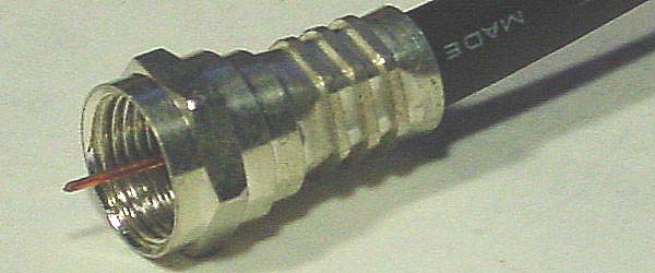
F-connectors
- The F-connector is the only
connector in common use for 75-ohm TV antenna systems.
There
is a quick push-on version of the F-connector, but these are never reliable
long term, even indoors. Even good
connectors require protection from the weather.
How long the cable lasts depends solely on how long you can keep water
out of it. 3M Vinyl Electrical Tape is a
good waterproofer. Cover the connectors
completely. Even better is an asphalt
putty called “Coax Seal”, but it is so tenacious it should not be used for
temporary connections.
It is
inadvisable for you to assemble F fittings onto coaxial cable. The result often proves unreliable over the
long run. It is better to purchase
ready-made cables of the proper length.
These machine made cables are highly reliable.
But
if you need an odd-length cable you might have to learn how to do this. Your first few cables will probably be
unreliable, but eventually you will get good at it. Don’t buy the smaller crimp tools. They will never make reliable crimps. Even the largest crimp tools will hurt your
hands. Leather gloves help. An extreme amount of crimping force is
necessary. Otherwise the junction
resistance will rise slowly over a period of months. Most importantly, get the right
fittings. There are three different
sizes, one each for RG59, RG6, and RG6QS.
This
author has not had good luck with screw-on fittings. Some people recommend RCA “Centerpin”
F-fittings and other easy-assemble fittings.
I have never used these “quickie” F-connectors, so I have no
recommendation on them. Even bad
connectors always work for a few months.
Then they start to fail intermittently in a manner that seems unrelated
to the connectors, causing much grief and wasted time. Just the possibility of this scares me away
from trying anything I have not used before.
Store-bought cables are safer.
Usually the only advantage of making your own is that you can drill a
quarter-inch hole, not a half-inch, through your roof.
Fading
- Depending on the terrain at
your location, there are often two paths for the signal to follow to your
antenna.
When
the sun warms up the land, a warm air layer near the ground can add a third
path. The warm air causes a bending
called refraction, which is identical to the “mirage effect”.
Which
of these paths will be the strongest is hard to predict. The ground-reflecting path is usually weak if
the reflection point is forested. The
bent path can be enhanced by focusing, making it stronger than the direct path.
These
paths will add together at your antenna, and considering phase, subtraction is
a possibility. Whether subtraction
occurs depends on the length of the bent path.
Since the warm air layer is always either growing (sun up) or shrinking
(sun down) this path length is always changing.
For UHF the path length need change by only ten inches to turn addition
into subtraction. If both path signals
are about the same strength, your DTV channel will dropout momentarily. If you see two dropouts that were N minutes
apart then you will probably continue to see dropouts every N minutes. This is fading. There is no cure for it, but a stronger
antenna will make it less likely.
The
above is but one scenario for fading.
There are many variations on this depending on the terrain.
FCC data base, accessing
- The FCC keeps an online
database for all its licensees, and it is relatively easy for you to use to
find a station’s location, transmitting power, and other data. Note that the accuracy of this data is not
guaranteed. And when it is accurate, it
tells what the station is allowed to do, not what it is actually doing.
1. Go to http://www.fcc.gov/mb/video/tvq.html
.
2. Type the letters of the station call
sign into the call sign box and press enter.
3. You will be shown a list of
records. Probably there will be from 1
to 4 records in the list. You should
select one of these records by clicking on it.
The status column shows the reason for the record:
- LIC -
Operating license granted.
- STA -
Special temporary authority.
(License granted with unresolved issues)
- APP -
Application for new transmitter submitted.
- CP -
Construction permit issued by FCC.
- CP MOD -
Construction permit modified
You should select the most recent record for the channel
number you want.
4. sometimes, instead of going to the
record you selected it goes to the first record and you must scroll down to the
desired record.
Interpreting
the record - The
FCC defines “Effective Radiated Power” (ERP) as the actual transmitted power
multiplied by the transmitting antenna’s gain (relative to isotropic, not in
dB) in its best direction. Antenna gains
of 10 are common, so the electric bill is not what the ERP suggests.
The
record will say whether the antenna is directional or omni-directional. If it is directional you can click on
“Relative Field polar plot” to see the radiation pattern. From this plot, find the field value for your
direction. Since this is a voltage
number it must be squared before multiplying it by the ERP to get the power
radiated in your direction.
TV Transmitting power allowed by the FCC - To make up for the
inability of UHF to reach into valleys, the FCC allows UHF stations to have
higher power.
Analog: DTV:
Channels 2-6 : 100 kilowatts 50 kilowatts
Channels 7-13 : 316 kilowatts 160 kilowatts
Channels 14-69 : 5 megawatts 1 megawatt
The above numbers are approximate.
The actual power rules are more complicated than this table, and
stations can argue for and get a higher limit.
But the goal in most cases is a 60-mile reception radius. Note that UHF transmitting antennas usually
have higher gain, so the actual disparity in transmitter power is not as great
as this table suggests.
Field strength meters
- Sometimes readers ask where
they can get a portable signal strength meter, thinking this will allow them to
make objective studies of the signal. A
signal strength meter is not as useful as you might think. The standard meter works well for analog
stations. But for DTV, a strong meter
reading is no guarantee that you have found a good reception spot if certain
types of multi-path are present.
An
additional complication is that there are two generations of DTV
demodulators. The newer generation
identifies the contributions of the weaker paths in a multi-path situation and
subtracts them out. A portable signal
meter based on one generation will not find the correct antenna
aiming/positioning when the TV’s demodulator is of the other generation.
The ultimate arbiter of where the signal is good for your receiver is the receiver itself. This author recommends that the signal strength readout provided by the receiver be used to search for the best antenna spots. The quality of the result justifies finding ways around the two problems you will discover when you try to do this. The first problem is that your HDTV is probably not on the roof, thus you can’t see the signal readout. The second problem is the receiver’s meter probably reads zero when it can’t demodulate the signal. This second problem is nasty for people in fringe areas. There are portable signal strength meters made for DTV, but they are rare and terribly expensive, and if they use a demodulation scheme different from what your receiver uses, their results might not apply to your receiver.
FM receiving antennas
- The FM radio band is 88-108
MHz, a 20 MHz band adjacent to channel 6.
Some VHF TV antennas work well over this band, but others don’t. There is no easy way to tell if a given TV
antenna will work well for FM. To
receive far away FM stations, you should probably get an FM Yagi.
Folded dipole
- The terminal impedance of a
folded dipole is four times that of a simple dipole of about the same
dimensions. Other ratios are possible by
using two rods of differing diameters, or by adding a third rod. The impedance of a freestanding half-wave
folded dipole is 300 ohms, but the presence of nearby elements will usually
lower this considerably.
Fringe area reception
- If you live in the fringe, you
can’t afford to make any mistakes.
You must find a mounting site that is high and not behind any trees. You might benefit by searching your property
for the spots with the strongest signals.
You need a Channel Master 7777 amplifier. You need the biggest antennas made. You might need single channel Yagis for
VHF. For UHF, start with a Channel
Master 4228 or a Winegard 9032. If with
this you don’t even get a digital lock then that station is hopeless. If you get a digital lock but you see too
many dropouts then consider ganging two antennas (see http://www.hdtvprimer.com/ANTENNAS/16bay.html
) Another improvement you can make is
to get a quieter amplifier. Research Communication in Kent England
makes a UHF amplifier with a 0.4 dB noise figure. It is expensive and takes some time and
effort to acquire but it will be like enlarging the antenna by 40%.
In
the fringe, weather affects reception.
You will never get dropout-free reception every day beyond 60 miles for
UHF, 80 miles for VHF, no matter how good your antenna is. Beyond these distances, dropout-free
reception on 9 out of 10 days is considered a good result.
Using
the above techniques, you can surpass what www.antennaweb.org
predicts for you. To force
antennaweb.org to give you a more optimistic prediction, find a house in your
area that is situated a little better than yours (higher and less obstructed)
and type in that address.
This page is part of “An HDTV Primer”, which
starts at www.hdtvprimer.com